Can You Test a Capacitor While It Is Still on the PCB?
You can screen a capacitor on an unpowered PCB, but an in-circuit reading does not necessarily describe that capacitor alone. Start with inspection and appropriate meter checks. If connected components can influence the result, isolate the capacitor before deciding whether it passes or needs replacement.
The distinction matters when you are learning how to test a capacitor on a PCB. A continuity beep can come from another component on the same supply rail. A normal capacitance reading does not rule out excessive equivalent series resistance (ESR). Even a low in-circuit ESR reading can hide a defective capacitor behind a parallel path.
Safety scope: this guide covers disconnected, low-voltage electronic assemblies whose stored energy you can safely identify and discharge using the equipment manufacturer’s procedure. It is not a procedure for mains power supplies, microwave ovens, flash units, electric-vehicle systems or high-energy capacitor banks. Low voltage does not automatically mean low stored energy. If the circuit or discharge procedure is unknown, stop and use a qualified technician.

A meter applies a test signal between two points. On a populated board, everything connected between those points can contribute to the measurement. Think of the probes as measuring the connected network, not selecting a single component just because their tips touch its leads.
Which Test Do You Need: Capacitance, ESR or Leakage?
Choose the test for the suspected failure: capacitance, ESR and leakage describe different behavior. Capacitance describes how much charge a capacitor stores per volt. ESR represents an internal loss component under AC conditions. Leakage is unwanted current through the dielectric under DC voltage. Passing one test does not establish the other two.
| Question | Useful tool or check | Important limit |
|---|---|---|
| Is there obvious physical damage? | Lighting and magnification | A flat, clean-looking capacitor may still have an electrical fault. |
| Is the capacitance near its specified value? | DMM capacitance mode or LCR meter, with the part isolated when required | Parallel components can distort the reading; compare under specified measurement conditions. |
| Are AC losses excessive? | ESR meter or LCR meter suitable for the part | Compare at the specified frequency. An ordinary DC resistance range is not an ESR measurement. |
| Is there a low-resistance path? | Resistance or continuity screening on the discharged board | A rail-level short does not identify which connected component caused it. |
| Does the dielectric leak excessively? | Controlled leakage testing against the component specification | This requires an appropriate setup and is outside this beginner procedure; ESR does not substitute for it. |
An ESR meter can be useful for installed electrolytics when its instructions allow in-circuit operation. However, the circuit still matters. The instrument manufacturer’s Siborg guide to testing without desoldering discusses why parallel paths and test conditions affect interpretation. Do not apply a generic ESR chart to every capacitor technology, value and operating frequency.
How to Test a PCB Capacitor, Step by Step
Use a progression from non-destructive inspection to isolated confirmation. Do not desolder every capacitor, and do not replace a part solely because one unexplained reading looks unusual.
1. Identify the board, component and expected value
Record the board revision and capacitor reference designator, such as C17. Obtain its capacitance, voltage rating, polarity, tolerance and manufacturer part number from the BOM or schematic. Small ceramic capacitors may have no readable value marking; guessing from their size is not reliable.
Check which components share its two nets. A schematic can reveal parallel capacitors, resistors or semiconductor paths that will influence an installed measurement. Without that information, record the limitation instead of assuming the part is isolated.
2. Remove power and verify the discharge state
Disconnect external supplies, batteries, USB cables and other possible backfeed sources. Follow the equipment’s approved discharge procedure with appropriately rated equipment. Do not short terminals with a screwdriver. No single resistor value or waiting time is suitable for every capacitor.
Verify the remaining voltage across the capacitor with a correctly configured, functioning meter before changing to resistance, capacitance or ESR mode. Meet the test instrument’s input requirements; do not treat an extinguished LED as proof of discharge. Recheck if the part has been left standing, because voltage can recover through dielectric absorption.
3. Inspect before applying test probes
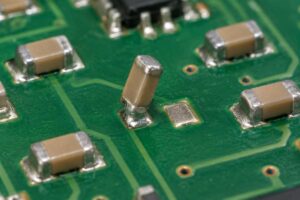
Look for a bulging or opened vent, leakage, cracked ceramic bodies, lifted terminations, corrosion and damaged pads. Photograph the finding. Flux residue is not automatically leaked electrolyte, and a dull lead-free joint is not automatically a failed joint. A damaged component should not be returned to service simply because its capacitance looks normal.
4. Make an in-circuit screening measurement
Use resistance mode only to investigate a low-resistance path, not to certify capacitance. Record the actual value and whether it changes with time; a beep alone loses useful information. Some low-voltage processor rails normally have low resistance, so compare with circuit information or a known-good board of the same revision before calling the rail shorted.
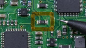
For ESR screening, follow the instrument’s lead compensation, connection and in-circuit limitations. Ensure clean electrical contact without scraping away protective coating or damaging pads. A comparison part is useful only when its specification and surrounding circuit are comparable. Label the result in-circuit screening, not component passed.
5. Isolate the capacitor if the result cannot identify it
For an individual capacitance check, electrically disconnect at least one terminal or remove the part, using a suitable rework process. Fluke’s capacitance-measurement instructions specifically call for detaching the capacitor to avoid measurement errors.
Do not pry up a cold surface-mount terminal or pull a through-hole lead from solid solder. That can turn a diagnostic task into pad or barrel damage. If you lack rework equipment or experience, hand the board to a technician with the screening record.

6. Measure, compare and record what remains untested
Select the proper mode, range and connections in the meter manual. For polarized parts, observe the instrument’s polarity instructions. Allow the reading to stabilize and compare it with the actual part specification, including tolerance and test conditions. For small capacitances, lead and fixture capacitance may need compensation.
If the meter reports an overload, check its measurement range and probe contact before blaming the component. Where needed, follow with ESR or other specified tests. Write down which checks passed and which were not performed. A component-level result is not yet a functional pass for the assembled board.
What Do the Meter Readings Actually Mean?
A useful reading has a measurement mode, a circuit state and a comparison limit attached to it. Use this table to decide the next check rather than turning every unusual number into a replacement decision.
| Observation | What it may mean | What it does not prove | Next action |
|---|---|---|---|
| Several installed capacitors beep across the same rail | The probes see a common low-resistance network. | All those capacitors are shorted. | Map the shared nets and localize the path before removing parts. |
| Installed capacitance is higher than the marked value | Other capacitors or circuit paths affect the reading. | The target capacitor increased in value or is healthy. | Isolate it for an individual capacitance measurement. |
| Capacitance is within tolerance | That parameter passes under the recorded conditions. | ESR, leakage and board operation also pass. | Test the parameter relevant to the symptom. |
| ESR is unexpectedly high | The part, contacts or test conditions need investigation. | One universal ohm limit applies to every capacitor. | Check contact and frequency, then confirm against the part specification. |
| In-circuit ESR is very low | The measured AC path has low apparent resistance. | The individual capacitor is good; another path may mask it. | Review parallel paths and isolate if confirmation is needed. |
| Capacitance mode displays OL | The value may exceed the range, contact may be poor or a fault may exist. | The part is definitely open. | Check range, connections and the meter manual; repeat isolated. |
| Ohms mode immediately displays OL | The meter detects no measurable DC conduction in that setup. | The capacitor is definitely open; a small good part may charge too quickly to observe. | Use an appropriate capacitance measurement. |
Worked Examples: Parallel Capacitors and Tolerance
First establish what is connected to the probes; then apply the correct numerical limit. These hypothetical examples illustrate the reasoning, not results from a QFPCB production test.
Two capacitors, one pair of test points
Suppose two ideal 10 uF capacitors connect between the same supply and ground nets. Their parallel capacitance is 10 + 10 = 20 uF. A measurement across either footprint sees both, not just the nearest body. A real populated board also has other paths, tolerances and instrument effects, so it may not display exactly 20 uF.
The same connectivity explains why a short elsewhere can produce a beep across every capacitor on that rail. Replacing all of them would be a guess. Identify the path first; an individual component verdict requires evidence that separates it from the rest of the network.
A 100 uF capacitor with a specified tolerance of ±20%
For this example, the capacitance limits are 100 × 0.80 = 80 uF and 100 × 1.20 = 120 uF. An isolated reading of 94 uF falls inside that interval. A reading of 62 uF falls below it, provided the prescribed test conditions are met and measurement uncertainty does not explain the difference. Readings near a limit need the instrument accuracy considered.
The 94 uF result still says nothing by itself about leakage or ESR. Likewise, do not apply this ±20% example to a part specified at ±5%, an asymmetric tolerance or another acceptance condition.
Ceramic capacitors need particular care. Murata explains that high-dielectric-constant ceramic capacitance depends on voltage, frequency, temperature and time. A room-temperature meter reading and the effective capacitance under operating DC bias answer different questions. Check the actual part data before rejecting a ceramic capacitor for reading below its nominal marking.
A Capacitor Test Record You Can Reuse
Record enough context for another person to reproduce the measurement. “C17 bad” is not a useful handoff; “C17 measured out of circuit, capacitance below its specified minimum under these settings” is testable.
- Identity: board revision, serial or lot number, reference designator and manufacturer part number.
- Symptom: what failed, when it occurred and whether it was repeatable.
- Safety and circuit state: sources disconnected, discharge verified, installed or isolated.
- Setup: instrument model, mode, range, frequency and test voltage where available, temperature and lead compensation.
- Evidence: photograph, actual reading with units, stability and comparison with a relevant known-good sample.
- Acceptance basis: datasheet revision, specified limit, tolerance and measurement uncertainty where significant.
- Decision: passed the stated check, failed the stated check, or inconclusive; next test and owner.
- Untested items: ESR, leakage, operating behavior or other requirements not covered by this measurement.
For a prototype PCB assembly, preserving this information before rework helps distinguish a component issue from a design, assembly or test-access issue. A failed board alone does not establish which one caused the problem.
PCB Capacitor Testing FAQ
Can I test a capacitor without removing it?
Often you can perform an initial screen, especially with an instrument intended for in-circuit ESR testing. You cannot assume that the reading belongs only to the target part. When connected components can mask or change the result, isolate the capacitor before making an individual pass/fail decision.
Does a continuity beep mean the capacitor is bad?
No. A temporary beep can occur while a capacitor charges from the meter, and a persistent beep on a board may come from another parallel path. Observe the resistance and circuit connections. Continuity is a screening function, not a measurement of capacitance, ESR or leakage.
Can a capacitor have normal capacitance and still be faulty?
Yes. Capacitance may be within tolerance while ESR or leakage fails its specification. A component can also behave differently under operating conditions than during a low-level bench check. Choose follow-up tests based on the symptom and component requirements rather than treating the capacitance display as a complete health certificate.
What ESR value means a capacitor is bad?
There is no single value for all capacitors. Technology, series, capacitance, temperature and measurement frequency matter. Use the manufacturer’s specification or a qualified comparison under matching conditions. A resistance value from a DC ohmmeter is not interchangeable with ESR from an AC measurement.
Why does the multimeter show OL?
Interpret OL in the selected mode. In capacitance mode, check the instrument’s range, contact and manual before declaring a fault. In resistance mode, OL does not prove an open capacitor: a small good capacitor may charge too quickly for you to see a changing display.
How do I check a small ceramic capacitor with no marking?
Find its reference designator in the BOM or schematic first. A package size does not determine capacitance. For an individual value check, use an appropriate isolated measurement and the part’s specified conditions. Also inspect for cracks, but remember that not all ceramic damage is visible from above.
What if my multimeter has no capacitance mode?
You can inspect the board and screen for a low-resistance path, but you cannot obtain a capacitance value from a continuity beep. Use a suitable capacitance or LCR instrument when that value is needed. Avoid improvised powered tests when the board or its stored energy is not understood.
Is replacing the suspect capacitor enough to confirm the repair?
No. Verify the replacement specification, polarity and soldering, then follow the assembly’s approved functional test. Also investigate why the original part failed. A capacitance test does not establish correct ripple performance, thermal behavior or operation of the rest of the board.
From a Suspect Capacitor to an Assembly Test Requirement
Turn the finding into a defined test requirement before ordering more boards. Specify the component, the suspected failure mode, the measurement conditions and what constitutes acceptance. Visual inspection cannot establish capacitance or ESR, while one electrical check cannot establish every aspect of reliability.
For a new PCB assembly project, share the BOM with manufacturer part numbers, schematic excerpt, affected reference designators, photographs and the test record. Include the required board-level function and any component-specific acceptance limits. Ask which checks can be supported and what fixtures, access points or customer procedures are needed.
Contact QFPCB with those files to discuss assembly and testing requirements. Confirm the available scope for your project; a component diagnostic guide is not a promise of repair service or a substitute for an agreed production test plan.